....take images of the moon! Last night, with the moon blazing bright in the night sky, I gave up on doing any DSO imaging after my test shots came out totally washed out in purple. I decided to take a few more periodic error measurements and call it a night early. But before that I figured I would try my hand at some moon images. Upon getting the moon in view of my DMK firewire camera I could tell this would be difficult because the moon was shimmering and shaking all over the place due to below-average seeing. The DMK camera is capable of higher frame rates to help get around the problem with poor seeing conditions. I bought the camera initially for dual-use as an autoguiding camera and a planetary camera. The folks at ImagingSource added long-exposure capability so now my DMK is a triple threat! So far I have only used the little blue camera for autoguiding. I am taking things slow and plan to tackle lunar and planetary imaging someday. For now I just recorded a few AVI files and ran them through RegiStax software, all the while not really knowing what I was doing. The results are not too bad considering the poor seeing conditions.
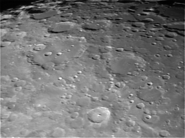
The first image shows the bright crater Tycho at the bottom, with south being up in this image. Crater Clavius is the large crater to the upper left of Tycho:
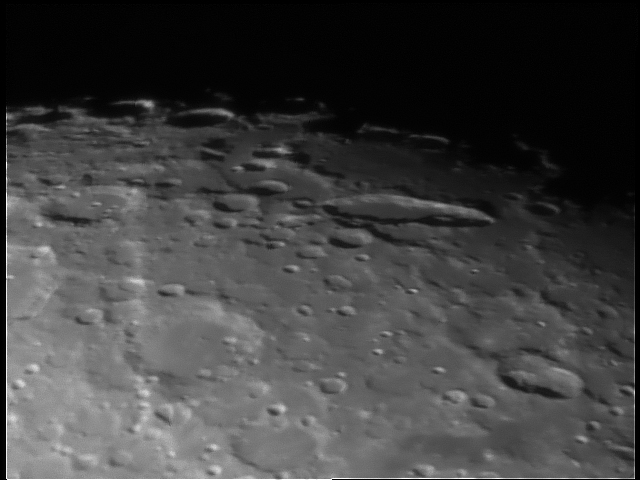
The next images moves a bit to the west, and shows one of my favorite lunar features, crater Schiller above and right of center. I have always found the elongated crater very interesting:
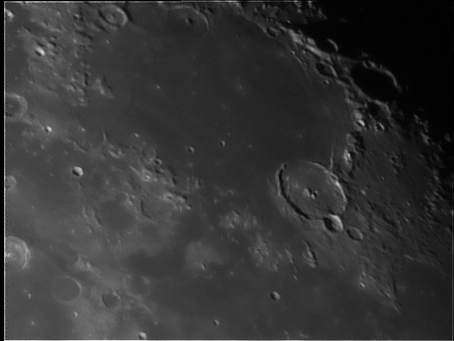
My final lunar imaging of the night moves a little north to another one of my favorite sites. This is the Mare Humorum area, with crater Gassendi to the lower right of center.
That's it for now. I still have a lot to learn about lunar imaging and working with the RegiStax software. But like I said before, I am taking things slowly, and one step at a time.
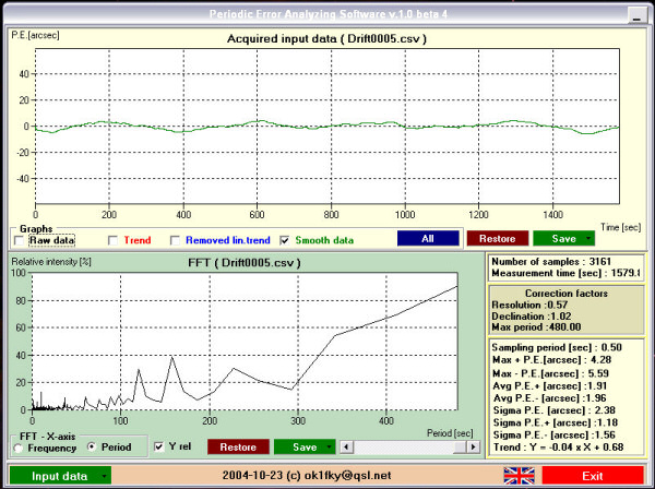
I got a brief period of clear sky a couple of nights ago. Less than an hour, but long enough to make a measurement of periodic error. To keep things fair with my pre-mod measurement, I used the same camera, scope, and software combination with all the same settings. I was using my DMK21AF04.AS CCD camera in the Celestron C8, with drift logging through K3CCDTools. Clouds started rolling in but I got enough data to plot in PEAS. Below is a screen shot from PEAS, and you can see that the "Max PE" values indicate a PE of a little less than 10 arc-seconds peak to peak. This is half of the pre-mod PE value. I'm pretty happy about the improvement - this is about the performance level of mounts costing twice as much or more. I'll keep on testing as weather permits.
...also known as "My EQ6 mount improvement - Part 3." When I received my mount back from Astro Motion Technologies it was immediately apparent that something was amiss in the operation of the mount's internal motors. The DEC axis would not move at all with a strange noise coming from the motor, and the RA axis would move less than halfway before stopping with the same noise. Here's a little video of the DEC axis trying to move:
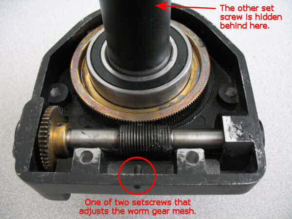
As you can see and hear there's no movement and the sound is very much NOT the typical whine of the motors that I am used to. Being an electrical engineer I was dreading the thought of troubleshooting something mechanical. I searched around the Internet and read everything I could about taking apart the EQ6. Then, with a little nervousness I began removing the DEC axis. It was really quite easy and well documented on other websites. Inside the DEC housing you can see all the major parts: the big brass-colored ring gear, the steel worm gear, the small brass-colored spur gear, and the tiny little set screws that become very important later.
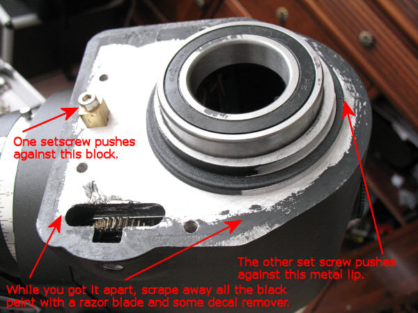
Those little set screws adjust the position of the worm gear relative to the larger ring gear. They actually move the entire housing, and since the worm gear is fixed to the housing you are moving the worm gear too. Below you can see what the housing sits on. There's a little metal block for one of the set screws to push against and the other set screw pushes against the metal lip around the large DEC axis shaft hole. You can also see the top of the gearbox which is driven by a stepper motor.
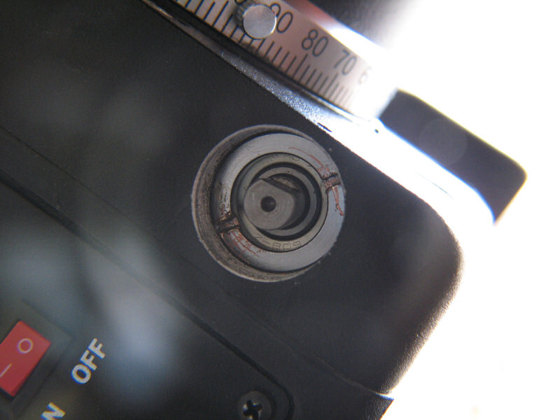
At this point it's a good time to scrape away all that black paint on the mating surfaces of the housing and mount. A flat razor blade and some sort of mild solvent will quickly remove this paint. I used decal remover. Removing the paint ensures that you have a tight fit and accurate tolerances. Now that I had the DEC axis apart I checked all parts and could find no problem. A bit puzzled, I put it back together. Another check of the motors revealed nothing new - still no movement. I then checked to make sure the stepper motor gearbox was making good contact with the spur gear. This can be done be removing a small screw under the end cap of the worm gear and looking in where the gears meet, as seen below:
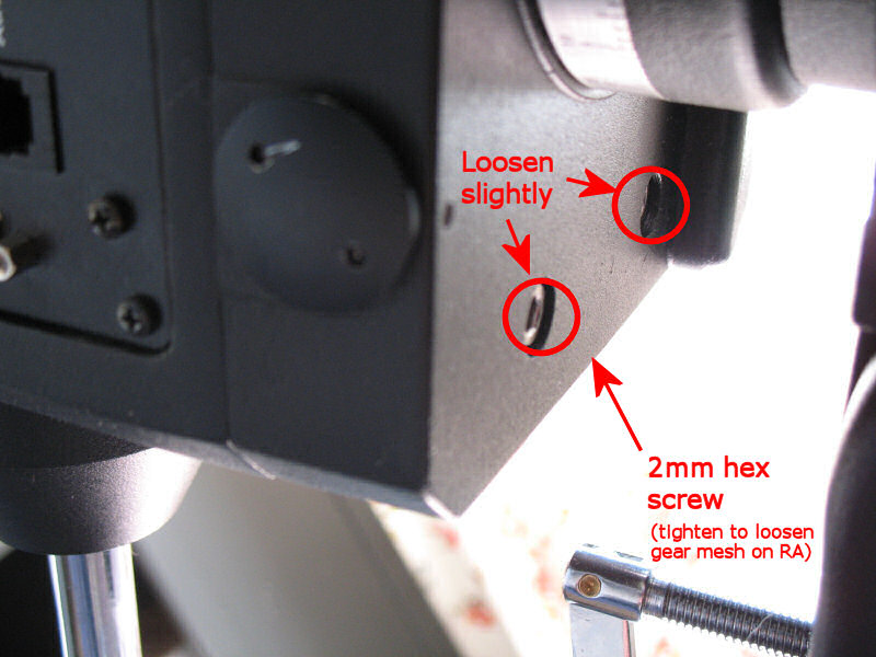
Everything looked good there, so it was back to the worm gear housing. By this time I had done a little more research, gotten some help from Tom at Astro Motion Technologies, and discovered the secret to the little set screws shown in the above pictures. To adjust, you first loosen the four 5mm bolts that secure the housing to the mount, but only very slightly:
The set screw shown above loosens gear mesh when tightened. The set screw on the other side tightens gear mesh when tightened, and is shown below:
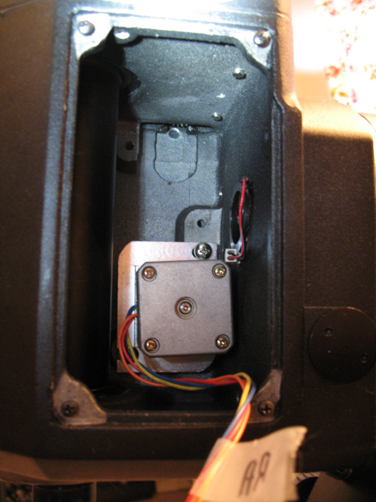
The best way to know when you are pretty close to having the right gear mesh is to remove the stepper motor for the axis you are adjusting and spin the spur gear with your finger. To accomplish this the electronics board of the mount is removed and disconnected. The stepper motors are behind this board, and easily removed with two screws. Below you can see the motor compartment with the DEC motor removed. The edge of the spur gear is just visible near the top of the compartment:
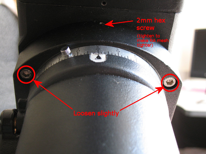
The spur gear should feel a little firm but not tight, and not very loose. Adjust the set screws until the spur gear is very hard to spin, then back off a little. Now you can put the motor back and check the gear alignment by peering into the hole shown previously. Then tighten the four 5mm housing bolts in a criss-cross pattern just like putting a tire on your car. Once I got to this point the motor still did not turn the DEC axis, which meant a little more adjustment of the set screws was necessary. The object here is to find the sweet spot between backlash and motor stall (what you saw in the video above). Backlash is "play" in the gears which you can feel by trying to rotate the axis with your hands while it is locked. If it wiggles back and forth - that's backlash. There's only a tiny spot between no backlash and motor stall, and it takes time to find. The gears must be checked across the full range of motion. They may seem fine at one point, then the motor might stall as you slew the axis around. Each time the set screws are tweaked, the adjustments are very tiny - just 1/8 of a turn or less. It turned out that I never needed to take apart the mount to make these adjustments, but I am glad I did. I really learned a lot in the process and am no longer afraid to dig into my EQ6. The RA axis is nearly identical as far as adjustments are concerned. Here you can see the first pair of 5mm bolts to be loosened just behind the RA setting circle, as well as the housing adjust set screw:
The other 5mm bolts and the other set screw are located down below the RA setting circle as shown below:
One other thing to check is the spanner nut at the end of each worm gear. These are behind caps located on the same side of the mount as the electronics board. The nut should be snug, but not too tight and not too loose. This is another source of play in the mount. The DEC axis spanner nut is shown below:
It took a couple of hours to get my EQ6 tweaked properly. Now I have no play in either axis and no motor stall either. With the WS2 coating I am even able to adjust beyond zero backlash. This means getting the backlash adjusted out, then tightening the gear mesh just a little more. This preloads the bearings and increases the contact area between the gears. I should get more payload capacity and better periodic error as a result. Thanks to Tom at Astro Motion Technologies for guiding me through all the adjustments and patiently explaining the reasons behind them. His help has given me a much better understanding of the mechanics inside my mount. We both now realize that all the electronics and hand control are needed for the WS2 modification. I didn't send my hand controller or electronics board with my mount, thus Tom could not operate the motors. He got the gears pretty darn close though! Now my mount is running smooth as silk. If these fierce winds ever die down I might actually be able to get out and test out the improvement. In case you want to hear what the mount should sound like, check out this video:
Last weekend I put together a couple of different stepper motor control kits to see how they each perform. The first was the CK1405 kit from Carl's Electronics. My assembled kit in it's testing configuration is shown below: I really wanted the CK1404 kit but they do not carry it any more due to the UCN5804B chip being discontinued. But, I also ordered another kit from Alltronics. Their kit did not have much of a description but I took a chance on it anyway. As luck would have it, their kit included the UCN5804B stepper motor IC and much more versatility in features. Back to the original kit - I tested it out and just could not get satisfactory operation of the motor. It was very "choppy" and did not have much speed adjustment range. I put that one aside and moved on to the Alltronics kit, as shown below: This kit worked very well. Motor operation was very smooth and there was a wide range of speed adjustment. Plus, this kit offers a low-speed mode, single-step function, half step mode, and a selectable full wave/2-phase drive. I decided to use the Alltronics kit for my design, which required some changes. Originally I intended to put everything in the hand-held case shown in my previous project post. But the Alltronics kit is too large to fit in that case. So the motor control kit will be mounted in a separate box at the mount. The hand-held case will just house the control switches and display. This design got me thinking - can I control three different motors with one control board? Why not? I have three focusers, so it sure would be nice to control them all. What I am planning is a relay switching circuit that only switches on one motor at a time. There's no reason to ever control two focusers at the same time, so this should work. My hand control just needs three more switches, each one to enable one motor. Below is my basic schematic of the motor control circuit, without all the hand controls and display: Also, over the weekend I built the display board, but have not yet tested it out: It's getting closer! My mount comes back tomorrow, so the focus control project will probably be sidelined for a while until we have some cloudy weather.